Tutorial and Plans for Building Your Own Horse
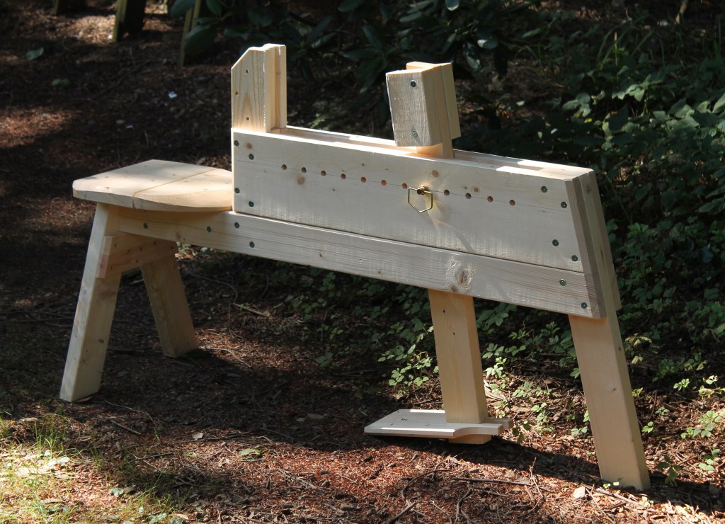
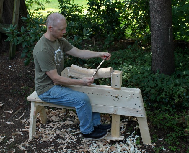
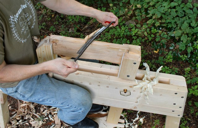
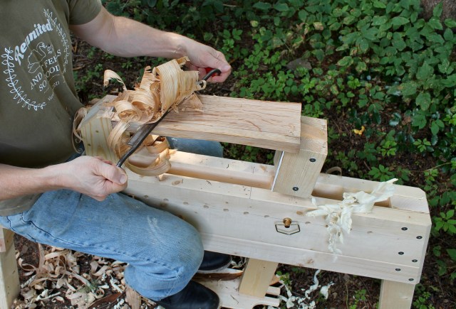
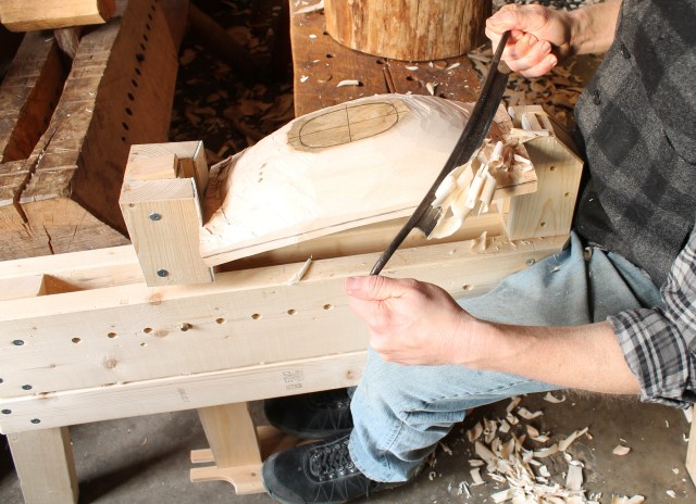
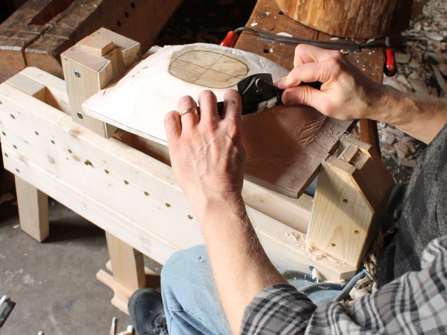
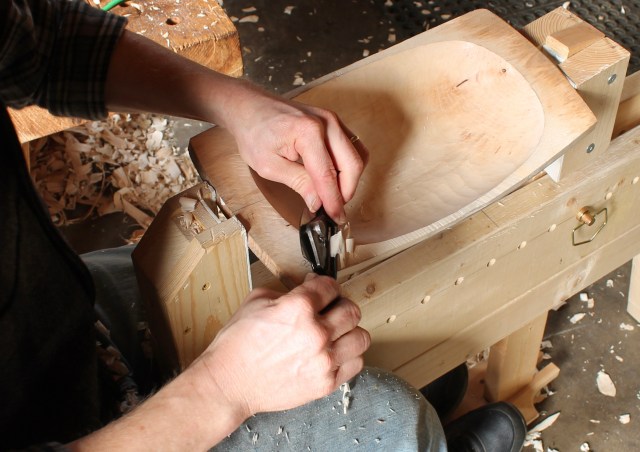
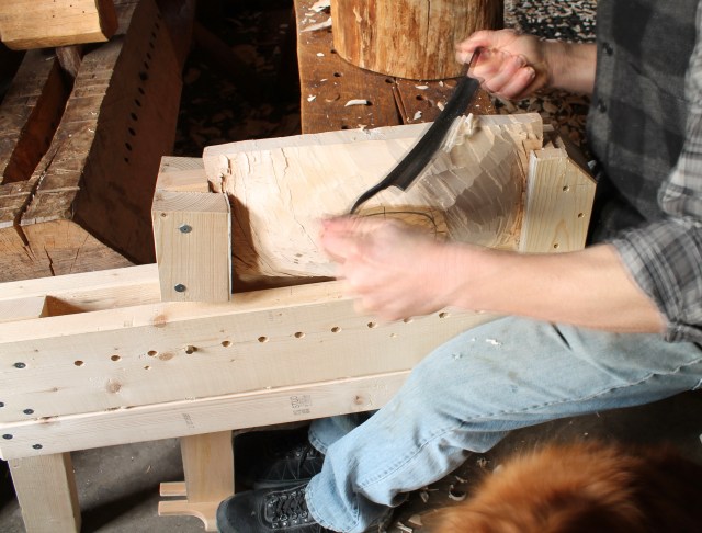
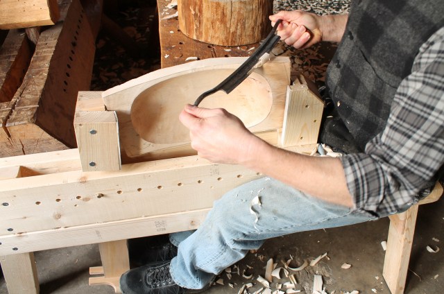
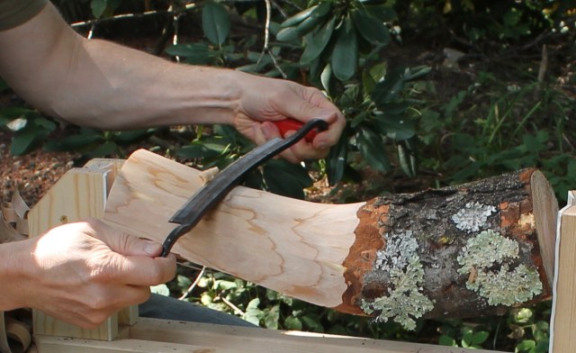
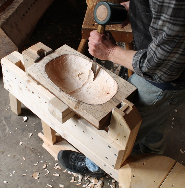
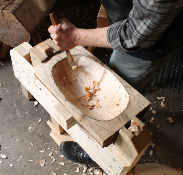
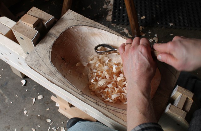
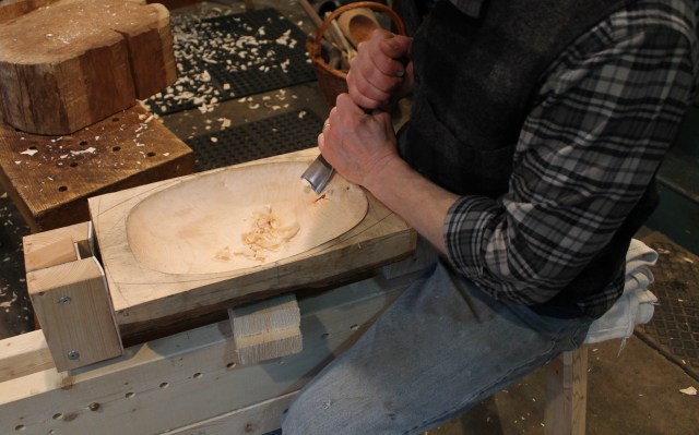
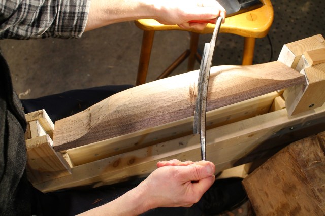
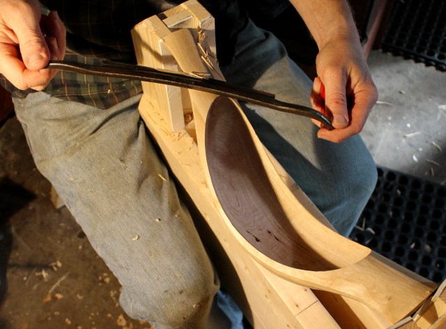
I designed and built my first bowl horse in 2004 and I’ve loved using it ever since. Although I call it the “bowl horse” because I depend on it mainly for bowl carving, I also use it for all sorts of woodworking tasks. The general idea has been around for centuries, probably millennia, in various forms. Put simply, it applies holding pressure end-to-end — horizontally, rather than vertically/downward as a more typical shave horse does. This version of the concept is especially robust. It holds securely, yet releases instantly, allowing pieces to be repositioned as you work. Design features allow it to self-adjust to odd shapes. Here’s a slideshow with some shots of the bowl horse in use:
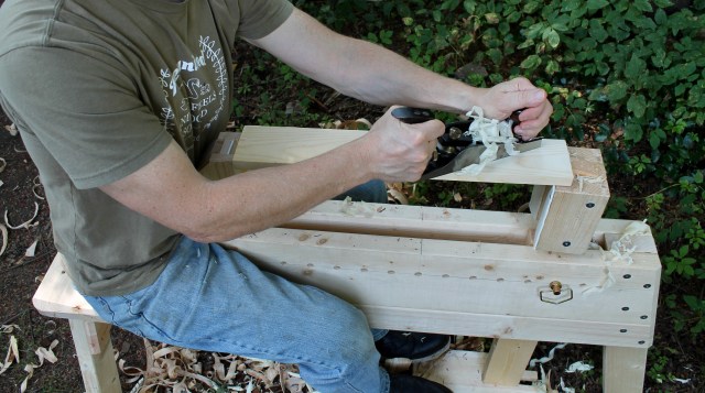

In designing this version, I’ve made it easier to build and improved its stability, versatility, and performance. You can build it with little expense or experience from common dimensional lumber. The plans and tutorial will take you through the process, and you’ll have a dependable carving partner for years to come. I hope it makes your woodworking time more productive and enjoyable.
The Plans were drawn by Jeff Lefkowitz. Jeff was able to convert my rough drawings and ideas into these beautiful and clear plans. You can download and work with them directly from your screen, or you may choose to have them printed at a local print shop. The intended size is 42″ x 24″ for the Elevations page, and 36″ x 24″ for the Parts page. If you decide to have them printed, it’s simple to email the files to the print shop and request that they be printed at the respective sizes above. Printing both sheets at my local shop cost a total of $10.

Get the Plans:
To access a PDF of the plans, click the button below. Once you make this one-time payment (this is not a recurring subscription), then you’ll be able to see the links to download the PDFs of both pages of the plans right on this page — like a curtain has been lifted. Any time you revisit this page, the plans will be visible to you. These plans are for your personal use. I’ve put a great deal of time and effort into their development; thank you for not sharing the files. The plans include:
- 1/2 Scale Elevation Drawings
- Full or 1/2 Scale Parts Drawings
- Detailed Dimensions
- Perspective Drawings of Horse and Parts
- Cut Diagram
- Complete Materials List
- Helpful Building Tips and Reminders
If you don’t have a WordPress account, you will be prompted to create one when you pay, which simply means providing an email and setting a password. That account will allow you to log in to the page any time. If the payment button doesn’t work for you, or if you would prefer to pay through PayPal, just send me an email at dandkfish@gmail.com. and I’ll get back to you right away with the plans. Thanks.
Step-by-Step Photo Tutorial
This detailed photo tutorial takes you step-by-step through the process of building the horse with (pretty) common tools. Combine the tutorial with the dimensions and information on the plan, and you’ll be able to build a solid horse that will serve you well.
You can cut the pieces as you go, or cut them all to starting size first based on the dimensions and cut list provided in the plan. A power miter saw will make quick work of this, and will provide true and square surfaces that will facilitate the build. Of course, you can adapt the methods based on your personal preferences and the tools available to you.
- Use a square to line up the two riser boards all around. If there is any bow in the boards and you have a choice, arrange it so that the two boards bow away from each other in the middle and touch at the ends. This will assure that the eventual channel will not narrow at any point. Connect the two boards with two three inch screws roughly toward the middle. These screws are serving as temporary clamps. Remember, throughout the build, safety first. Use eye protection and other common sense precautions.
The wood I am using in this tutorial is commonly available “whitewood” (spruce or white pine). You should be able to the lumber for under $30. The finished product with all hardware weighs about 36 pounds and is plenty strong. It’s also easy to pick up and transport. If you want a little extra heft and strength, then southern yellow pine would be a good choice.
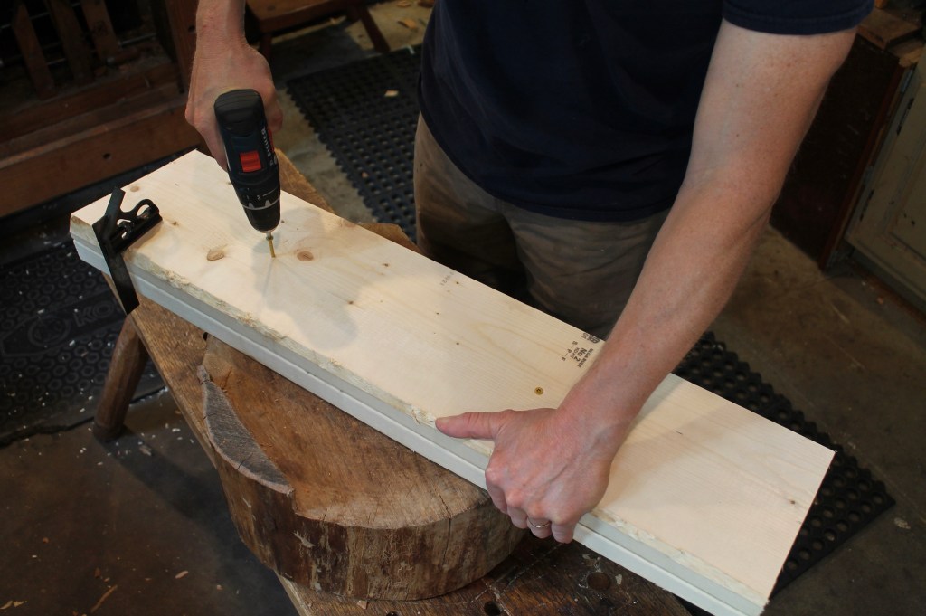
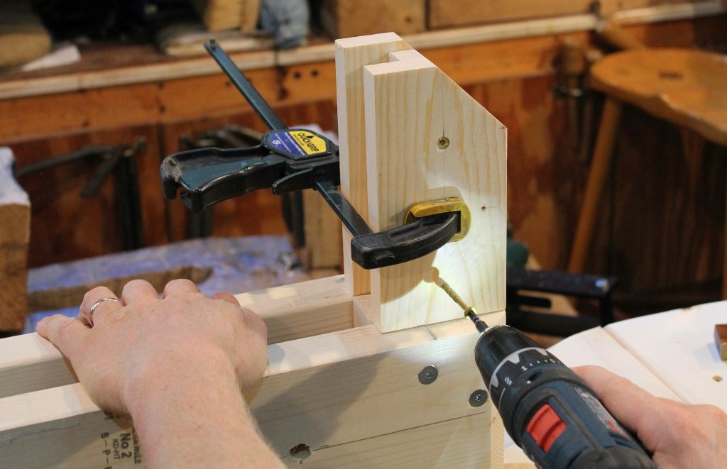
2. Mark the hole locations according to the plan, on both sides of the riser sandwich. Drill the holes halfway through, using a square (or two) for reference to keep the holes perpendicular to the riser faces. I used a sharp spade bit. You’ll feel it when the bit reaches the joint between the boards; stop there, halfway into the sandwich.

3. Once you’ve drilled all of the holes halfway from one side, flip the boards over and do the same from the other side. When the bit meets the hole drilled from the first side, lift the boards up and continue through into the hole previously drilled. This method aligns the holes to account for any slight variation in the drilling angles and hole locations and works very well if you mark things accurately before drilling. If you have a drill press, you could drill straight through in one shot with assurance that the holes will be at 90 degrees to the board faces.
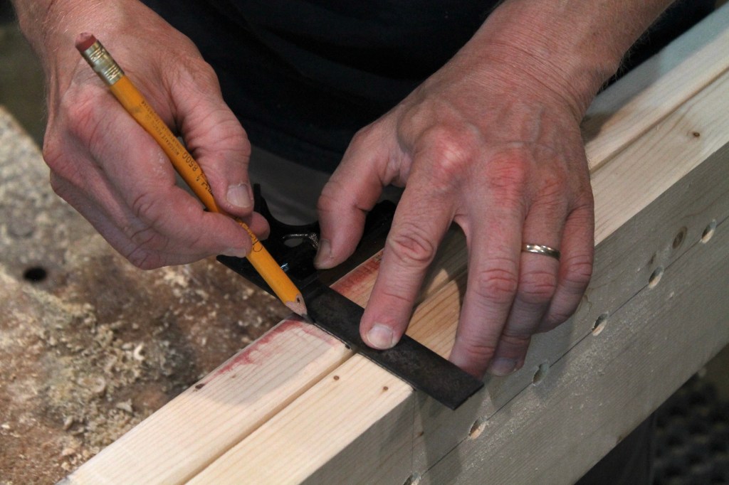
4. Before separating (by removing the two screws connecting) the boards, draw a reference line square across the top sides of both boards. This will be used later to make sure the holes line up again after the risers are assembled.

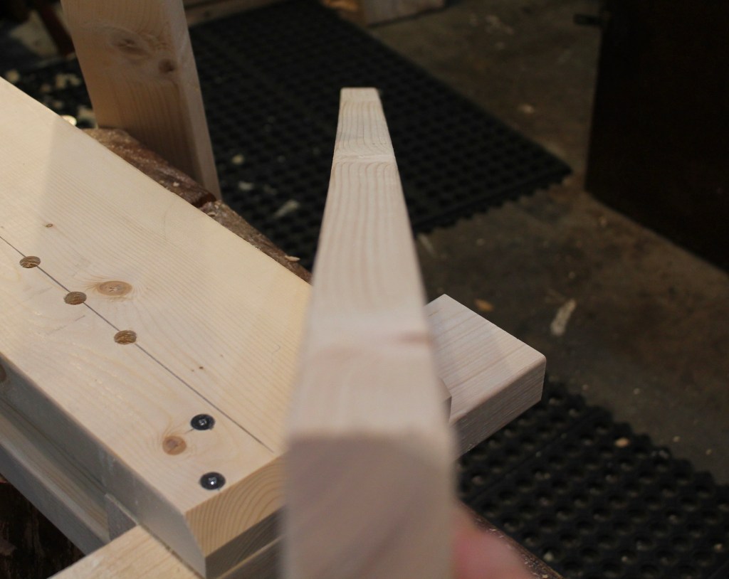
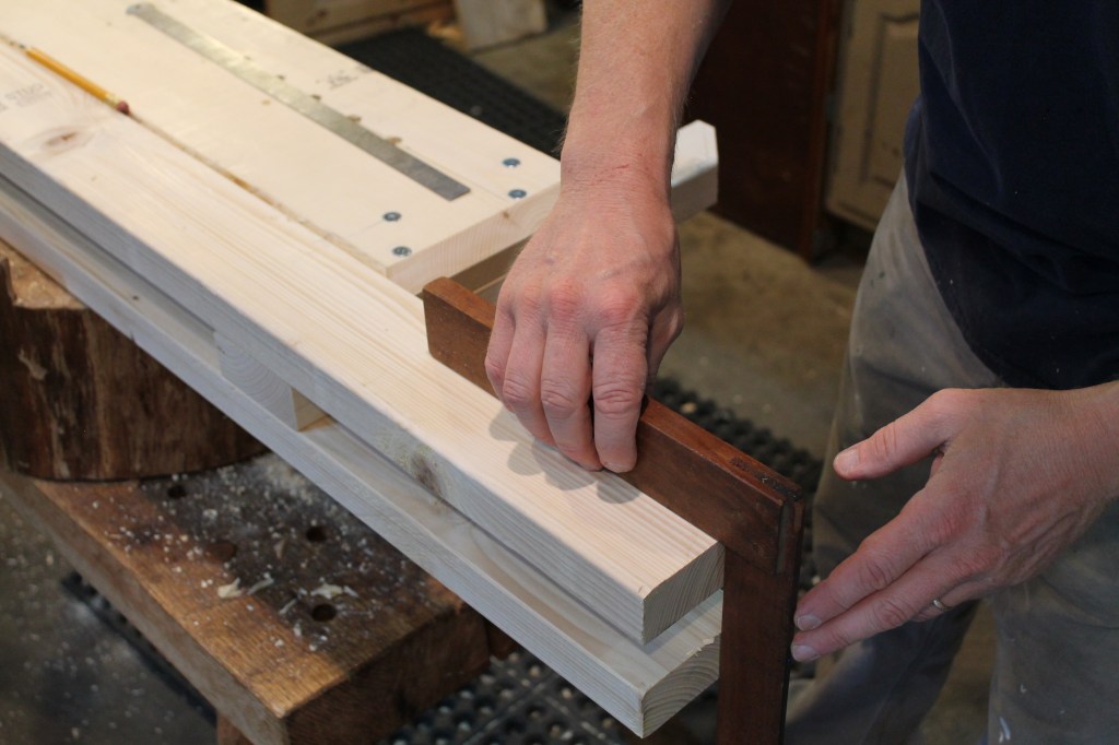
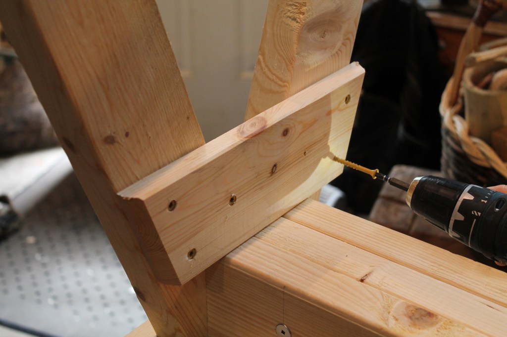
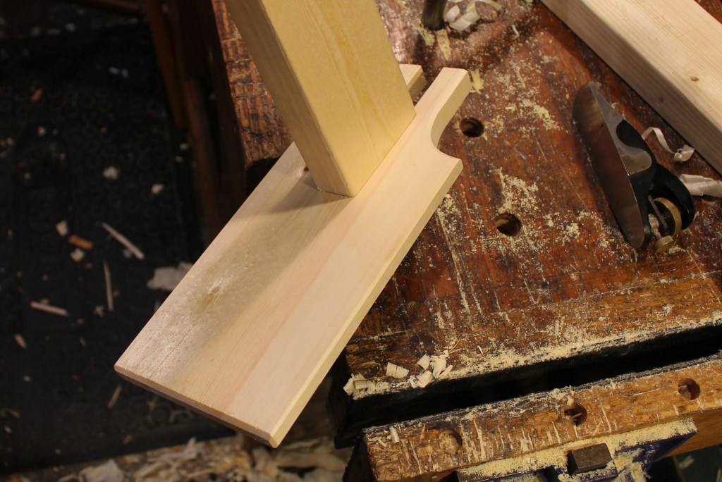
5. Remove the two screws and sandwich the front leg and stationary head, according to the arrangement on the plan, between the riser boards. Clamp them loosely for now.

6. Take the time to make sure the top surfaces of the riser boards are parallel by using a square registered on the face of a riser. The blade of the square should sit against the top of both risers. Check that the stationary head and front leg are in line with the edges of the riser boards. Notice that I had not cut the notch in the front of the stationary head at this point. I should have, and I did so before driving the screws.

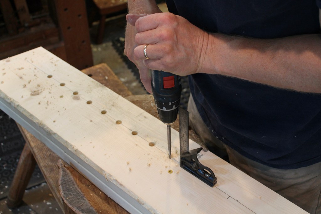
7. The reference line drawn before will help to assure that the holes will line up across the gap. Use a square to make sure the reference marks are in alignment across the channel. Once everything is as it should be, tighten the clamps, then begin to drive the screws.

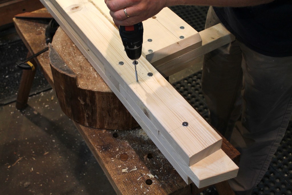
8. Drive the 3″ screws at the locations indicated on the plan, connecting both risers to the stationary head at one end and to the front leg at the other end. As is noted on the plan, the screws have opposite arrangement on the other side so as not to meet head-on in between. Once you’ve got a couple screws in at the ends of both risers, the clamps can be removed to provide access for the remaining screws. (Notice, the notch in the front of the stationary head has been cut.)
Regarding the Screws: For many of the screws in this project, I used “Powerhead” wood screws by FastCap for the holding power provided by the wide head. You’ll also find similar washer-head screws at home centers, like these. If you’d prefer a black oxide finish, here’s a link to some. I do think these wide head screws offer improved performance in soft wood like this. That said, normal #10 3″ deck screws would work well too, so use what you have or can get without too much trouble. 11 of the 3″ screws need to be “normal” bugle head deck screws. You’ll see further along in this photo tutorial where I used these. There are also 13 2″ deck screws required. The plan will indicate where to use 2″ and 3″ screws, respectively.
Use caution whenever you are installing a screw within an inch or two of the end of a board. There is potential for the screw to act as a wedge and run a split. In soft wood like this, with screws that have self-drilling tips, you’ll usually have no problem, but it never hurts to drill a pilot hole the size of the screw shank in the top board. Use your judgement and try a test on a scrap.

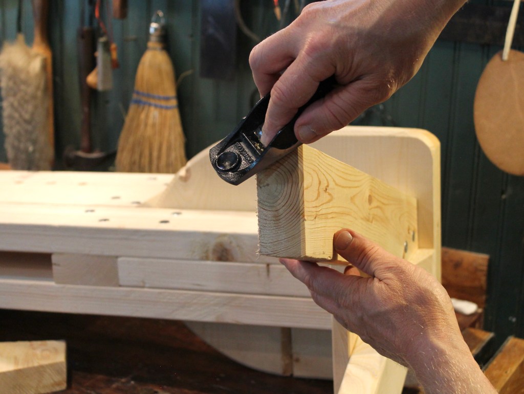
9. Plane the large chamfer at the stationary head end as indicated on the plan.
10. Examine the two beam boards for any bow. As with the riser boards, position any crown toward the outside so as not to narrow the channel. In the example above, the right side of the board will face out.
11. Attach the first beam to one side according to the location on the plan. Line up the edge with the front leg and keep it tight to the riser board above it. Flip the piece over and use a square to line up the back end of the second beam with that of the first beam.

12. Attach with 3″ screws at the locations indicated on the plan.

13. Tap in the seat keel between the beams. Keep the front edge tight to the lower portion of the stationary head post.

14. Use a straightedge to make sure the upper surfaces of the seat keel and the beams are flush all along.
15. Secure the seat keel from both sides with 3″ screws at the locations indicated on the plan.

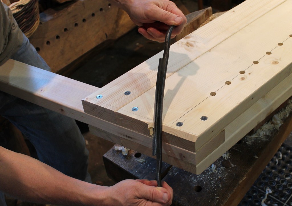
16. Mark the front seat board according to the pattern on the plan and cut the outer curve. You could use a band saw, jig saw, bow saw, or a hatchet and drawknife. Drawknife the large curving chamfer to the lines on the upper and side surfaces. This eases the area where your legs go over the seat and it looks good, too. Ease the sharp bottom edge of the seat board by creating a small chamfer.

17. Drawknife the large upper chamfer on the rear seat board as well, then attach both seaboards with 3″ screws at the locations indicated on the plan. Attach the front board first, centering it and butting the front right up against the stationary head assembly. Then butt the rear seat board right up against the front seat board. Eventually a little gap will open up between the seat boards as the lumber dries. No problem. Here, I’m using normal 3″ deck screws, rather than the Powerhead screws, so that the heads can be sunk just a touch below the surface. If the seat keel should stick out a bit beyond the rear of the seat, just trim it off flush to the seat.
You could simplify the shaping of the seat by just cutting the front of the seat off at a 45 degree angle on both sides. I did that on a prototype, but it looks clunky and doesn’t feel as good. I found that the combination of curves and chamfers is more comfortable and looks much better. Shaping the seat this way is not much trouble. Indeed, it’s a joy and a good opportunity to use a drawknife. Up to you; you can always remove your first seat and add an upgraded one someday if you want.

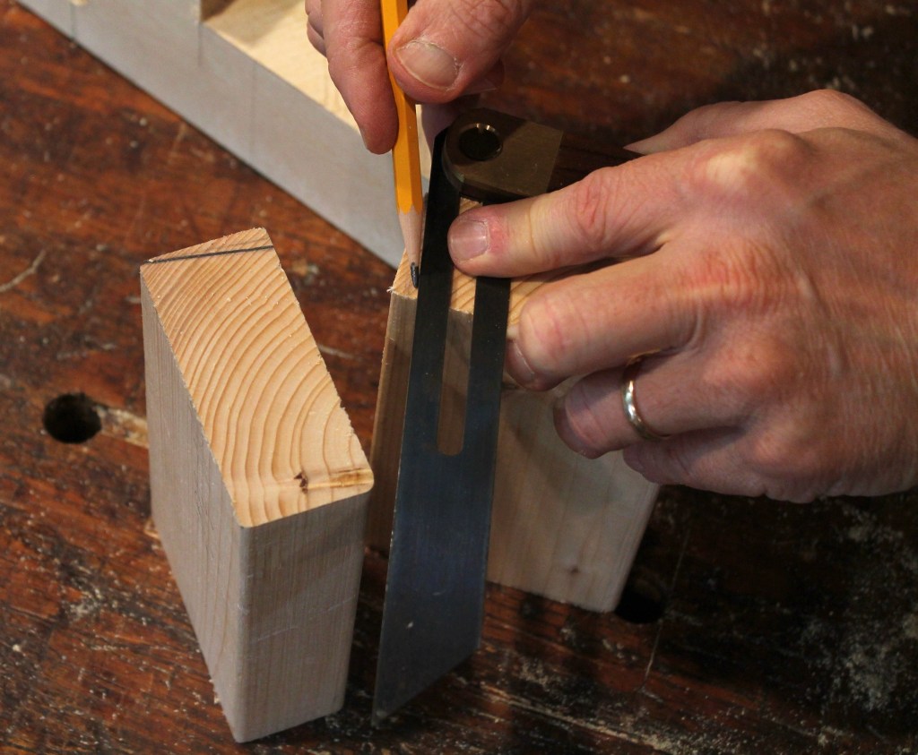
18. The upper end of the rear legs get two angled cuts. These cuts need to be true and square. A miter saw makes quick and accurate work of these and requires no explanation, but you can do them just as well with a saw and a plane if you take your time. Here’s how to go about it that way. With a bevel gauge and a pencil, mark the angles according to the plan. Cut the upper side first, leaving a little material to fine tune with a block plane. Check the angle with the bevel and use a square to assure that the cut is square to the face.

19. Cut the cheek of the rear leg with the saw, again leaving just a little material to allow for fine tuning.

20. Plane the sawn surface so that it is square to the upper surface and to the face.

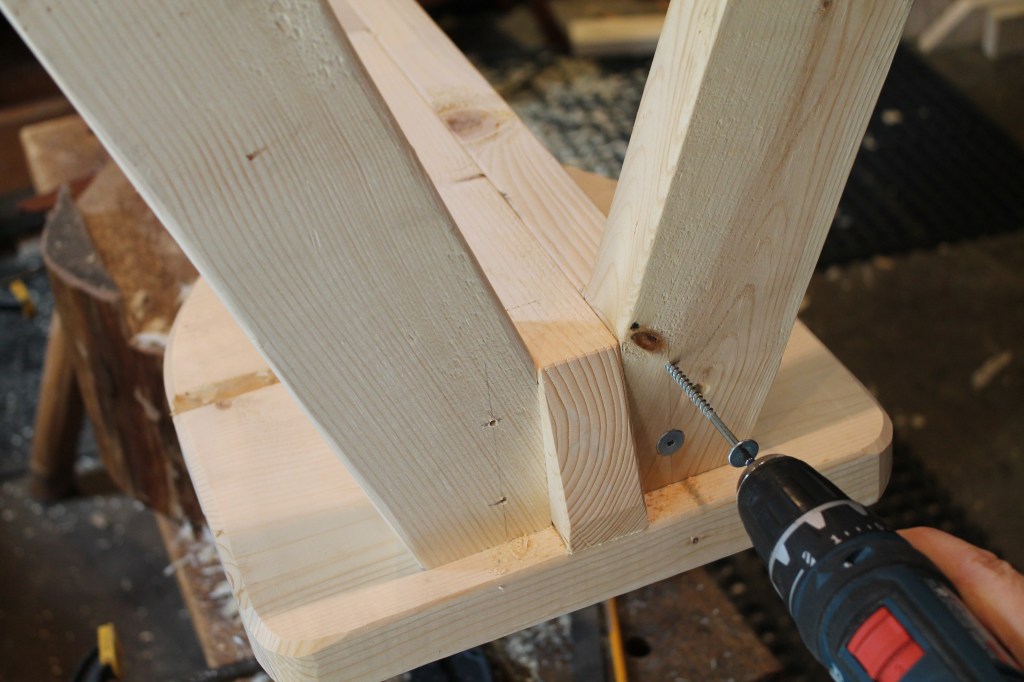
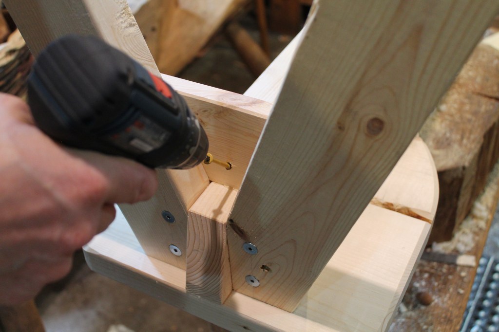
21. Hold the leg tightly into the corner pocket created by the junction of the beam, the seat keel, and the seat. A momentary assist from a passerby can be a big help here. Drive a normal (bugle head) 3″ deck screw through the seat keel and into the center of the leg cheek, sinking the head just below the surface of the seat keel. An alternative method for attaching this first leg is shown in step 22 (below) for attaching the second leg and it assures that the leg is pulled tightly into the corner. Either way, use a regular bugle-head deck screw for this step so that the head can go just below the surface of the wood.

22. With the other leg in place, drill a pilot hole and drive a 3″ screw at an angle through the rear face of the leg and into the seat keel. Your aiming point is the junction of the seat keel and the beam. This will pull the leg into that pocket. Make sure the leg is down against the seat as well. This method could also be used to attach the first leg as an alternative to the method shown in step 21.
23. Reinforce the leg connection by driving two 3″ screws through the leg faces (at the locations indicated on the plan) and into the ends of the beams.
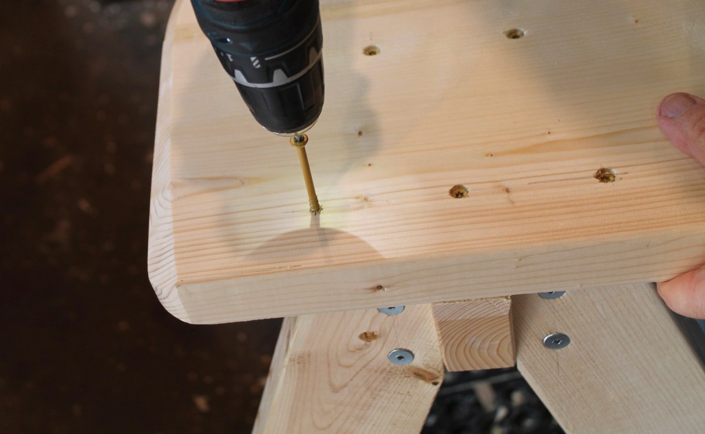
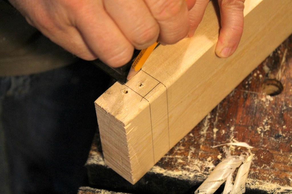
24. At the locations indicated on the plan, drive two 3″ screws through the seat and into the upper surface of the rear legs.

25. Place the board for the rear leg gusset down against the surface created by the beams and seat keel. Trace the outer edges of the rear legs onto the gusset board.

26. Cut to the outside of these lines and chamfer the corners a bit.
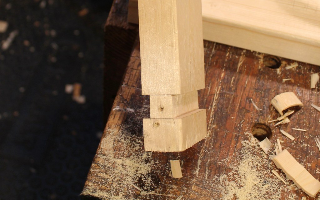
27. Use 2″ screws at the locations indicated on the plan to secure the gusset to the forward faces of the rear legs.
28. As one last assurance that these legs aren’t going anywhere, drive a 3″ screw at approximately a 45 degree angle through the back face of the leg gusset and into the seat keel.
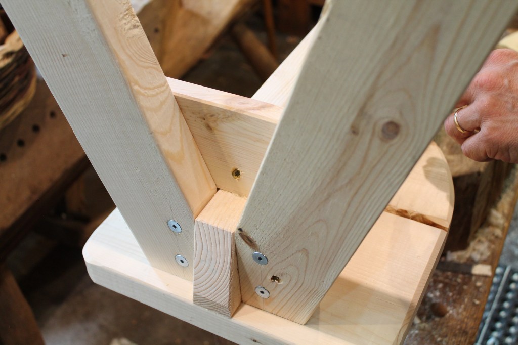
29. There. The legs are more than ready to hold you solidly off the ground.

30. Now it’s time to trim the bottom of the legs so that the horse sits level and plumb. My shop floor isn’t very flat, so I placed the horse on my workbench. You want to use shims of one sort or another under the legs until the horse is sitting level and plumb. I began by checking level from front to back by placing a spirit level on top of the risers.

31. Next, I checked for plumb against the side of the horse. This can be tweaked by adjusting the shims under either the right or left rear legs.
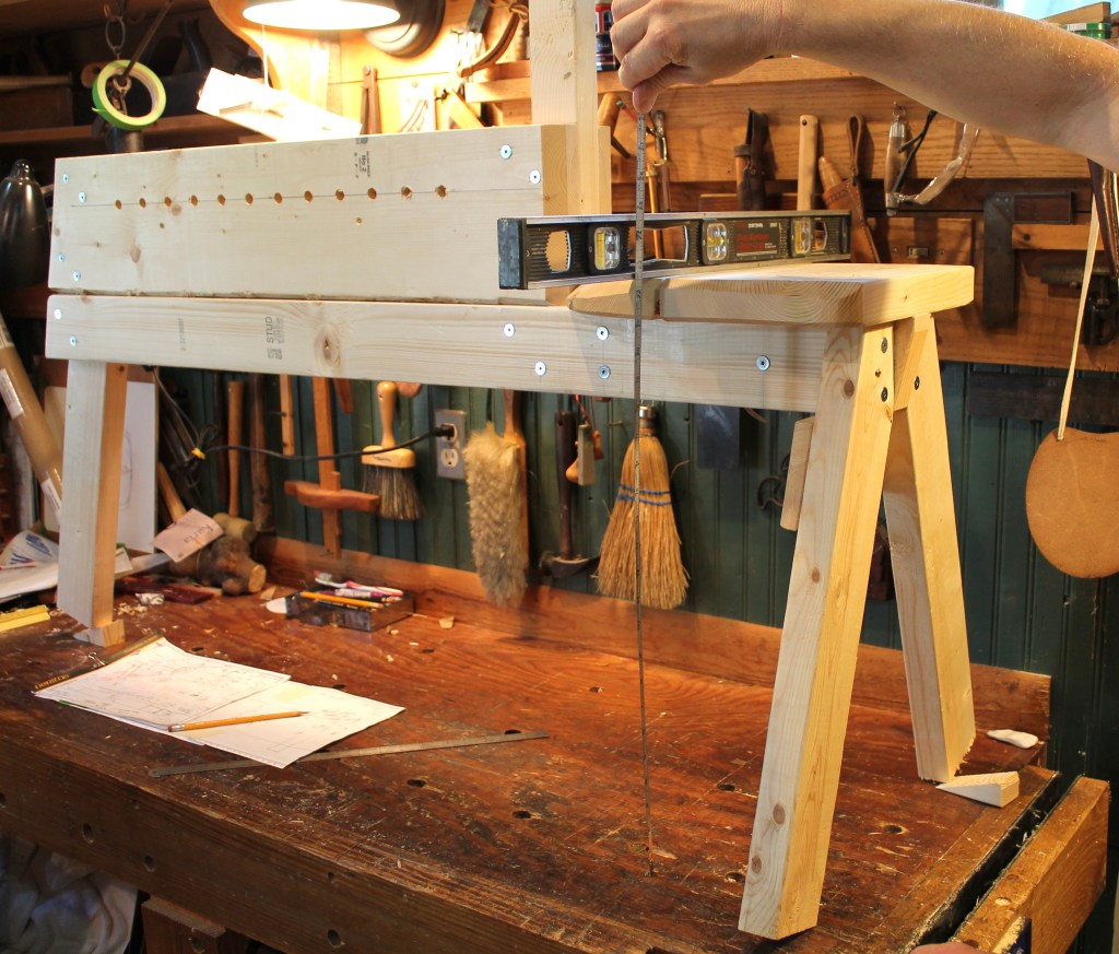
32. Once the body of the horse is level and plumb, it’s time to mark the bottom of the legs parallel to the workbench surface or whatever flat surface you are using under the horse. But we’ve got to establish the height first. Extend a straightedge beyond the seat and measure to the bench top. Write that measurement down. Let’s say it’s 22 1/2″.
For a person of average height/leg length, I would suggest a 19″ seat height for this horse. I’m about 5′ 10 1/2″ with a 32″ inseam and it works well for me. Don’t overthink it, because it would probably work well for just about anybody, but if you’re particularly tall or short, you could increase or reduce the seat height accordingly. Maybe go down to 18″ if you’ve got short legs and up to 20″ if you’ve got long ones. If you do so, add or subtract an inch to the swing arm length indicated on the plan, because it corresponds to a seat height of 19″.

33. Now, back to that theoretical measurement from the seat to the bench top of 22 1/2″. Since we want a seat height of 19″, subtract 19″ from 22 1/2″. The difference is 3 1/2″. Use a block of wood, a compass, a stack of books, or whatever you may have that you can lay a pencil across with the point held 3 1/2″ (in this case) above the workbench. Use this gauge to go around all three legs marking them parallel to the bench and 19″ below the seat top.
34. Cut the legs off just below the line. Trim to the line with a block plane if necessary.
35. Chamfer the bottom edges of the legs to prevent splintering and splitting. These surfaces will hold up well enough, but I later added some rubber bumpers to mine for protection and to keep moisture from wicking up through them as much when I take the horse outside. I cut pieces from a rubber horse hoof pad (which seemed appropriate) that I had around, like these. I glued them on with CA glue (superglue). They raised the horse up a 1/4″ and that’s no problem. If you decide to add something to the bottom of the legs, you could probably also use what you have around, like an old rubber door mat. Or just leave them wood and they’ll be fine.
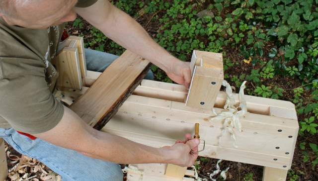
36. Attach the stationary head cheeks with 2″ screws. Don’t use glue. Over time, these cheek pieces may get chewed up a bit by the edge of the drawknife and they can be easily replaced. In use, you’ll find that the screws are firm, but allow the cheeks to move just a bit to adjust to variations in the workpiece. A serendipitous discovery!

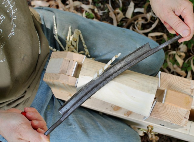
37. Attach the stationary head face. In the photo above, this piece is 3/4″ thick. 1/2″ is a little better because it makes the channel a bit deeper. I removed it and planed it down to 1/2″. Since the screw head is in the channel, there is no chance of a drawknife edge coming into contact with it later.
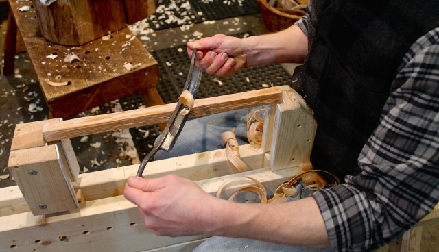
38. Cut the large chamfer at the front of the horse. Above, I’m using a drawknife to remove most of the material.

39. You could also use a block plane to form the chamfer.

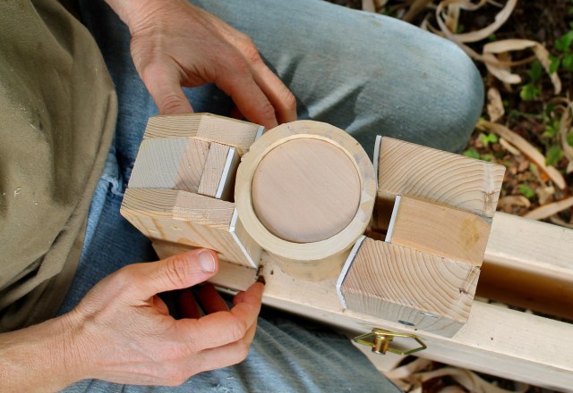
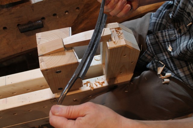
40. Now, on to the swing arm. First, plane the swing arm to the thickness indicated on the plan. This gives the proper clearance in the channel to allow the arm to rack slightly and adjust itself to odd shapes of workpieces. Then cut the notch in the top of the swing arm and drill the two pivot holes. Importantly, wiggle the drill bit around a little to flare the holes slightly. This gives the swing arm some play on the pin, which, again, allows the swing arm head to pivot from side to side and self-adjust to curves and odd shapes that may not be positioned perfectly square to the axis of the horse.
41. Now it’s time to make and attach the swing head cheeks. I want the face of the cheeks to taper inward in order to “capture” odd shapes and hold them toward the center. This works especially well to grip the curved ends of bowls, but also for many other things. It also works well for pieces that are flat, but if you ever do want to use the flat face on the back of the swing head, you can simply flip the (reversible) swing arm around. More about that later.
Mark the angle on each end of both cheeks as shown above. Lacking a bevel gauge, you can simply use the measurements on the plan and connect the two marks across the end with a straightedge.

42. Plane to the lines. This bevel can be flat or slightly crowned.

43. Position the cheeks on the swing arm and screw them in place with 3″ screws according to the plan.
44. The foot board will attach to the swing arm by sliding into two dadoes. This allows the footboard to be removed and flipped around to the other side if the swing arm is reversed. Mark these dadoes according to the measurements on the plan. It is better to err on the side of marking the dadoes a wee bit narrower (rather than too wide). If necessary, the foot board can always be planed down a few shavings to fit snugly into the width of the dadoes.

45. Cut the dadoes with power tools if you’d like to and know how. Cutting these dadoes by hand is straightforward if you take your time. To cut the dadoes by hand, strike the shoulders of the dadoes with a square and knife. Then cut at an angle from the inside of the dado to those vertical knife cuts to create a small channel for the saw.

46. Saw down to the depth of the dado.

47. Remove the wood between the saw cuts with a chisel, working down to full depth straight across the board.
48. With both dadoes cut to dimension, the swing arm is ready to receive the footboard. All that’s left is to cut the footboard.
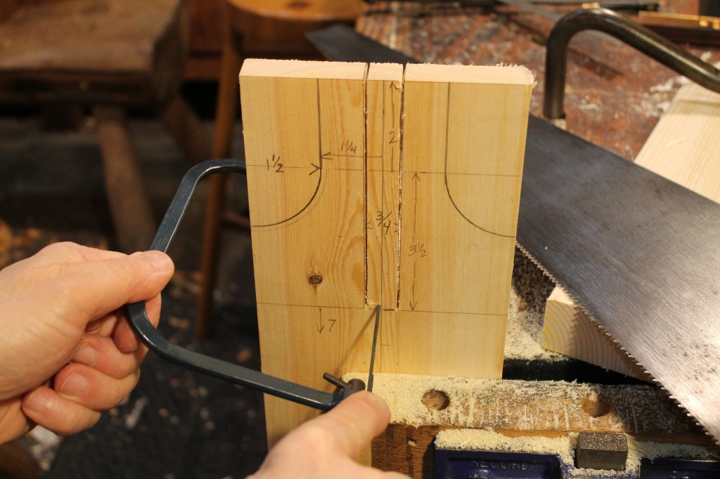
49. I used a 1×6 (3/4″ x 5 1/2″) for the footboard. If you want a wider footboard, just use a 1×8 or whatever. Regardless, the important thing is to carefully cut a slot down the center according to the dimensions on the plan. I cut the sides of the slot with a handsaw then used a coping saw to go across the bottom to finish. Lacking a coping saw, you could use a chisel, removing material from both sides of the board.
You could leave the foot board just like that and all would be fine. I chose to relieve the corners to the sides of the slot by cutting away the two half-U shapes you can see above.

50. You can further refine the foot board with some chamfers that will prevent splintering and lighten things a bit. I put some small chamfers on the top side and large chamfers on the bottom. That’s the bottom side facing you in the photo above.
51. Check the fit and adjust accordingly until the footboard slides into place firmly with a bit of pressure. If needed, you could secure the footboard with a pin or bit of wood running just behind the swing arm across the extended wings of the footboard. However, if your joinery is tight, the footboard will stay in place solidly by friction alone.
This assembly allows the footboard to be driven off and installed on the opposite side of the swing arm. Then the swing arm can be installed “backwards” in the horse to use the flat side of the swing head for certain operations if so desired (although it’s probably unlikely that you will so desire). This opposite side of the head could be customized in various ways through shaping or the addition of materials. Maybe abrasive paper or even a series of metal teeth. Or a nail could be added to hold one end of a piece to be rotated while shaping.

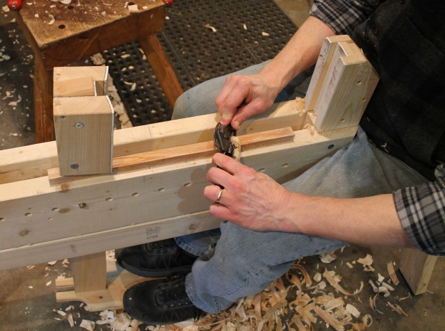
52. For the swing arm pivot pin, a 1/2″ hitch pin like this works perfectly. You’ll find slight variations in appearance and details at various hardware stores, but the shaft will be 1/2″ diameter and this one has a perfect length of 4 1/2″ from the shoulder on the right to the edge of the chamfer on the left. But any 1/2″ diameter rod will do.
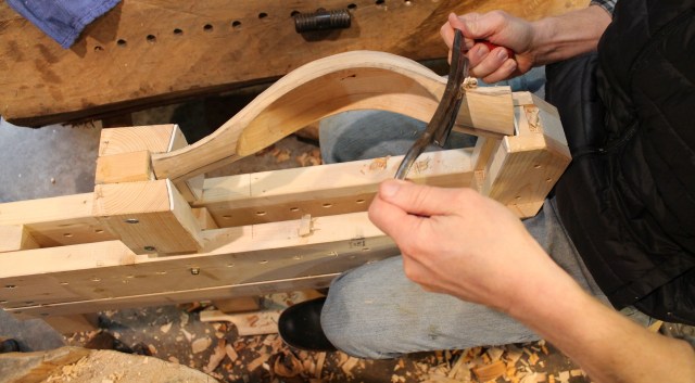
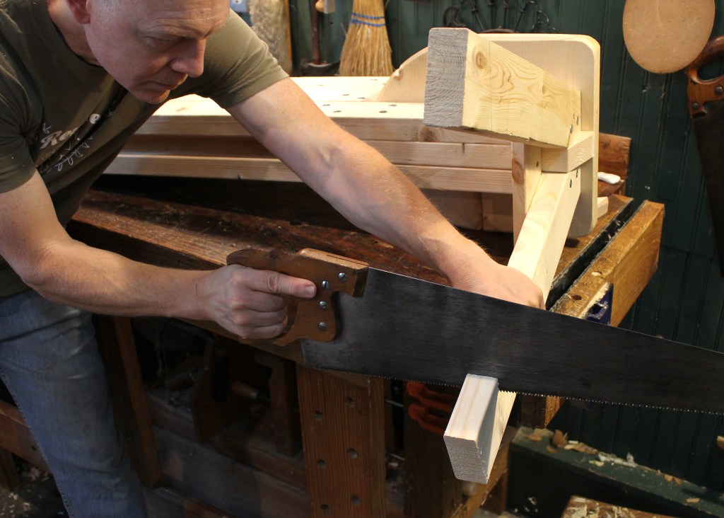
53. There it is in place. The spacing of the holes in the riser, combined with the two hole options in the swing arm, allows the swing head to be moved in 1″ increments to hold workpieces as long as 22 1/2″ right down to the jaws touching each other.
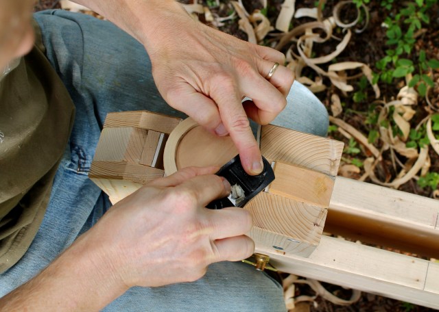
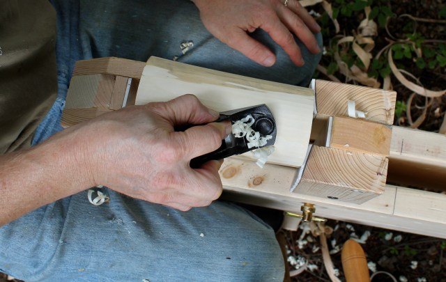
Notice that I cover the the faces of both heads (stationary and swing) with rubber. This dramatically increases the grip and reduces the pressure needed to hold pieces securely. There are lot’s of materials that will work. I’ve used old rubber floor mats and even shoe soles. The best option is probably adhesive backed neoprene rubber 1/8″ thick. Here is a link to one brand, but there are many others. It works great for many other shop uses as well, including vise jaw liners. You could also try Crubber. I wish leather gripped as well as rubber, but it doesn’t, especially over time. And the grip is important so that you can use less pressure and reduce unexpected slips.

54. Now you’re ready for years of riding and carving on your own horse. For a bit of extra style and fun, add reins and name it.
